#Project report on decimal to bcd priority encoder k map code#
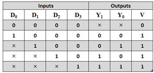
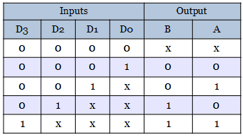
The main characteristics of this encoder include cascading for priority encoding of n bits, code conversion, priority encoding of highest priority input line, decimal to BCD conversion, output enable-active low when all the inputs are high, etc. Add the symbol for the priority encoder to the Block Diagram File. An IC 74148 is the most popularly used MSI encoder circuits for the 8 to 3 line priority encoder. The add file to current project box should be checked Figure 12.9 Saving the Block Diagram File 10. Make sure the box labeled Add file to current project is checked. the D flip-flop holding Q1 state) with a JK flip- flop, and the Qz flip-flop with a T flip-flop. Redesign this circuit by replacing the Qr flip-flop (i.e. Drive a state table and draw a state diagram for the circuit. Truth Table – For common cathode type BCD to seven segment decoder: drive:qdesignslabslab12BCDpriorityBCDpriority.bdf Figure 12. ECE124 Digital Circuits and Systerns, Final R.eview, Spring Z0ll Q1Forthefollowing clocked sequential circuitwith one input (X)and one output (Z): 1.

This BCD to seven segment decoder has four input lines (A, B, C and D) and 7 output lines (a, b, c, d, e, f and g), this output is given to seven segment LED display which displays the decimal number depending upon inputs. First, our decimal number is changed to its BCD equivalent signal then BCD to seven segment decoder converts that signals to the form which is fed to seven segment display. Common Anode Type: In this type of display all the anodes of the seven LEDs are connected to battery or +Vcc and LED displays digits when some ‘LOW’ signal is supplied to the individual cathodes.īut, seven segment display does not work by directly supplying voltage to different segments of LEDs.

Here in the given figure, one case is highlighted when D7 input is ‘1’ all outputs a 1, b1, and c1. Common Cathode Type: In this type of display all cathodes of the seven LEDs are connected together to the ground or -Vcc(hence,common cathode) and LED displays digits when some ‘HIGH’ signal is supplied to the individual anodes. As shown in the figure, the input-output waveforms look similar to the decoder because the encoder is just the reverse of the decoder.ISRO CS Syllabus for Scientist/Engineer Exam.ISRO CS Original Papers and Official Keys.GATE CS Original Papers and Official Keys.


 0 kommentar(er)
